• Products
    Braids & Terminated Braids BamControl Cables Data and Instrument EMC/VSD Cables Flexible Earthing Cables SafeX125 – Halogen Free Cables High/Low Temperature Cables Extra Low Voltage Cables Marine Cable Audio Equipment Cables Mining Cable Power Cable – LV-Flex Pump Cable PVC Flexible Rubber HO7 RN-F Communications (Telephone) Cables Roadway Cables Railway Cables Solar Cable Silicone
  • Industries
    Automotive Communication and Data Building and Construction Automation and OEM High Temperature Specialist Cables Marine Mining Navy – Defence Power & Transmission Rail Solar Traffic and Roads Wholesale
  • About Us
    Company Overview Our Commitment Bambach Manufacturing Bambach History Testimonials Latest Catalogue Custom Made
  • Wire Wizard
  • Contact
  • Company Overview
  • Products
  • Industries
  • Custom Made
  • Wire Wizard
  • News
  • Contact
HO
Bambach Sydney
102 Old Pittwater Road,
Brookvale. NSW 2100
Sales Enquire Via State

A Guide to Quality Cables

Author: AWD Digital

A Guide to Quality Cables

Posted on 30/05/201930/05/2019 by AWD Digital

We use cable every day in our lives more than you may realise. It carries power to our computers and phones, helps kick start our cars in the mornings and of course lights up our homes. If there is a disruption in the supply of power or signals it can be inconvenient or dangerous.

Conductor Centre

It is a requirement to have a minimum radial thickness of insulation and sheath on the conductor or cable. The amount required is governed by various factors such as insulation type and voltage. If the conductor is off centre, the insulation thickness may be below the minimum threshold. If the insulation thickness is too thin, it can break down during operation and cause a fault or arc. For instrumentation and signal cable, an off centre conductor will increase unbalanced capacitance and degrade signal quality. The same principle applies to the sheath thickness.
To apply a quick check, square cut a cable length and inspect the cable. If the insulation and sheath looks fairly evenly distributed around the conductor or cable, then it should be ok. If there is a noticeably thin and thick section, there could be an issue.

Conductor Area

Conductor area is important to carry the minimum continuous current and provide suitable maximum voltage drop. The associated conductor size for current ratings and voltage drops can be found in AS3008.1.1. If there are a few strands missing from the conductor, this will reduce the CSA (conductor surface area) and increase resistance. If a 2.5mm² conductor carries the same continuous current with reduced CSA, it will be operating at a higher temperature. If the cable is carrying the maximum prescribed current, then the temperature will be higher than the rating of the insulation. If this is the case, the insulation will degrade quicker and could actually melt away, exposing the conductors.

Reduced CSA’s also have an effect on the voltage drop and power consumption. The voltage drop is proportional to the resistance, so a 2.5mm² carrying 20A at 240V has a voltage drop of 5% at 33.3m. If the conductor resistance is increased by 10%, the voltage drop at 33.3m will be 5.5%. As the voltage drop is higher, there will be less voltage at the load and therefore less power i.e. it will take longer to boil the kettle.There are 2 ways to check that the conductor is the right size. Firstly count the number of wire strands in the conductor. Then measure the diameter of the wire using a vernier or micrometer. You can apply the formula to calculate the conductor area.

CSA = πr² * No. of Wires

The number of strands and diameter can also be checked against the products data sheet.The second method that can be done is to measure the conductor resistance using a multimeter. The total resistance will need to be divided by the cable length to get a per metre value. This value can be checked against maximum values found in AS/NZS1125

Insulation Resistance and Core Continuity

Conductors are insulated so that they can be protected from each other. There can be faults when there are fluctuations or holes in the insulation. If the cable has a shield or braid, it is more likely that there will be continuity between the braid and core rather than core and core. It is also important that the cores and shield have continuous continuity through out the run. Cable can be supplied with joins buried in the reel. Cable continuity can is an issue where the join only becomes obvious after the cable has been reeled off the drum,
To check that there is no continuity between the cores and shield, use a Megger Resistance Tester to check the resistance value. The test can be carried out in various ways such as core-core, core – all cores or core – screen. The longer the length of cable, the lower the resistance value will be. Different insulation materials will also have different dielectric strengths. As a guide, the resistance value should be in the 10’s of MΩ to GΩ. Continuity of cores can be checked using the Megger Resistance Tester or a multimeter. In this instance, the desired resistance value is low. Once again the value found is length dependant. As a guide, if the resistance value is in the MΩ, there will probably be an issue.

General Feel and Appearance

There is measuring and testing that can be done on cable to determine its quality but a simple general inspection is all that could be needed. Cables are generally intended to be round however they can end up ropey, snakey and odd shaped. An un-round cable could cause issues when terminating through a gland. The material can be checked by the general feel of the cable. By rubbing or cutting the material, it can give indication of the quality. For example, poor quality silicone is very soft and when rubbed, it wears away. Like anything you buy, you can get a good sense of the quality just by having it in your hands.

Media Release: Recall Too Restrictive – All Infinity And Olsent Cable Should Be Removed

Posted on 30/05/201930/05/2019 by AWD Digital

28th August 2014

With Reference to ACCC Product Safety Recall Notice dated 27th August 2014
RE: Infinity and Olsent Brand TPS and Orange Circular Electrical Cables

While the ACA acknowledges and supports the proactive approach taken by the ACCC in an attempt to remedy this serious safety issue caused by the importation into Australia of sub-standard and dangerous cable manufactured in China, the ACA contends that the Recall does not fully achieve its objectives.

The ACA is of the view that the wording of the Recall is complicated, confusing and too restrictive.

The Recall places the onus of action to rectify the dangerous condition of this cable upon the consumer or more simply the home owner. Typically, home owners would not be aware of which type or brand of cable they have installed in their house. Cable is hidden away in wall cavities and roof spaces making it ‘out of sight, out of mind’; this in no way diminishes the risk of having this dangerous product installed in a house, dwelling or any other type of building.

The meaning of the Recall wording is such that, in reality, there is practically no situation where the dangerous and defective Infinity or Olsent cable could remain in service.

The Recall notice should be clear and direct that ALL Infinity and Olsent Cable must be removed forthwith.

The initiator for the removal of all cable subject to this Recall must be the installer, as opposed to the consumer, since he is, in reality, the only person who will have sufficient knowledge regarding the location of the dangerous and defective cables.

About the ACA and the Approved Cables Initiative

The ACA established the Approved Cables Initiative (ACI) to address the existence of dangerous, non-compliant and counterfeit cable in the Australian marketplace.

It was the ACI who first alerted the Authorities to the dangerous Infinity and Olsent cable.

The ACI runs an extensive testing program of both Australian and foreign manufactured cables being sold in Australia.

The ACI’s mandate is clear: Any and all cable failing to comply with the Australian Standards will be reported to the relevant State and Federal Authorities who have the power to instigate a recall of such products in the interest of community safety.

For further information please contact:

David Klarich
ACA Secretary
(02) 9600 0277

Wire Wizard

Posted on 01/08/201901/08/2019 by AWD Digital

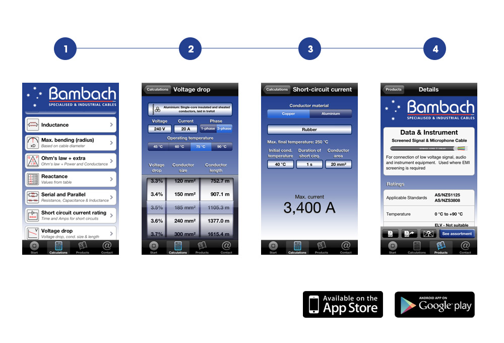
Wire Wizard is a back pocket tool containing helpful electrical calculations such as voltage drop, current carrying capacity, AC resistance, max bending radius, characteristic impedance, short circuit current rating, ohms law and many more.

Targeted at electricians, engineers and other electrical enthusiasts, Wire Wizard is a tool designed to assist the appropriate selection of wires and cables according to the Australian and New Zealand standard AS/NZS 3008.1.1:2009.

Wire Wizard is now available on iphones, Androids and other devices using the web version.

1

Calculations on the go including: AC resistance, capacitance, characteristic impedance, condustor size, current-carrying capacity, inductance, max. bending radius, ohms law (+ power and conductance), reactance, serial and parallel resistance, capacitance and inductance, short circuit current rating and voltage drop.

2

Wire Wizard displays an easy to read table describing the relationship between voltage drop %, conductor size and cable length. Assisting in your selection of appropriately sized cables.

3

Calculate the short circuit current rating for either Copper or Aluminium conductors. The calculation considers the selected insulating material as well as the initial temperature, the duration of the short circuit and the conductor size.

4

Brought to you by Bambach Wires and Cables, Wire Wizard contains Bambach’s latest product catalogue and contact details. Bambach’s technical sales team are happy to assist you in the selection of the most appropriate cable to suit your application. 

Wire Wizard Calculations Explained

Posted on 01/08/201920/06/2020 by AWD Digital

Bambach have launched a Smartphone app called Wire Wizard.

This document will help answer questions you may have on:

  • How to use the app
  • The common scenarios where the app may be useful
  • Instructions on how to use the app and interpret the results

Voltage Drop

Common scenarios requiring voltage drop

  1. Determining the maximum distance that a cable can be run before it exceeds the maximum allowable voltage drop.
  2. Determine the minimum conductor size to run a given length
Instructions – Scenario 1 – Determining maximum length
  • Choose appropriate conductor size based on installation conditions and required current. See current carrying capacities.
  • Input supply voltage, current and whether its 3 phase or single phase
  • Choose the operating temperature. The operating temperature is often not known however the maximum operating temperature is. PVC is rated to 75°C, X-90 90°C etc. By inputting the maximum operating temperature, you are determining the worst case scenario for voltage drop.
  • Choose the maximum allowable voltage drop in the first roller (5% is maximum under installation guidelines).
  • Choose the appropriate conductor size based on current carrying capacity in mm² (found in point 1).
  • The maximum conductor length will be displayed in metres
Instructions – Scenario 2 – Determining minimum conductor size
  • Choose appropriate conductor size based on installation conditions and required current. See current carrying capacities.
  • Input supply voltage, current and whether its 3 phase or single phase
  • Choose the operating temperature. The operating temperature is often not known however the maximum operating temperature is. PVC is rated to 75°C, X-90 90°C etc. By inputting the maximum operating temperature, you are determining the worst case scenario for voltage drop.
  • Choose the maximum allowable voltage drop in the first roller (5% is maximum under installation guidelines).
  • Choose the required conductor length in metres.
  • The minimum conductor size to run the length will be displayed.
  • Check that this minimum conductor size is equal to or greater than the conductor size found in current carrying capacities. Both parameters need to be satisfied.

Short Circuit Current Rating

Common scenarios requiring short circuit current raiting

  1. Calculating permissible conductor short-circuit currents for majority of practical cases
Instructions
  • Select the conductor material type
  • Select the insulation. Each insulation type is rated to withstand a certain conductor temperature. The higher the temperature, the higher the current rating. The corresponding maximum temperature for each insulation material is displayed underneath the insulation designation.
  • Select the initial conductor temperature. This could be selected as ambient (considered to be 40°C) or the worst case scenario. The worst case scenario would be the temperature at which the conductor is carrying maximum load. i.e. PVC is 75°C, XLPE 90°C.
  • Select the permitted duration of the short circuit in seconds
  • Select the conductor area in mm²
  • The maximum current is displayed below in Amps

Current Carrying Capacity

Common scenarios requiring current carrying capacity
  1. To determine the maximum current that can be carried in a given cable and installation condition
  2. To determine the minimum conductor size to carry a required current in a given installation condition
Instructions – Scenario 1 – Determining maximum current
  • Select the insulation. Each insulation type is rated to withstand a certain conductor temperature. The higher the temperature, the higher the current rating. The corresponding maximum temperature for each insulation material is located next to the compound designation.
  • Select the cable type. The earth core does not count as an active core. For example a 2C + E orange circular cable would be considered a 2C sheathed cable.
  • Select the installation type. This is where the user will install the cable. If half the length of cable is exposed to the sun, then the entire length should be considered to be exposed to the sun.
  • Select conductor material. This is broken up into 3 choices. Cu solid/stranded relates to non flexing copper conductors (for example orange circular). Cu flexible is copper conductor with flexible stranding (for example panel flex). Aluminium relates to aluminium conductor.
  • Lastly, select the conductor size of the cable in mm²
  • The maximum current will be displayed in Amps
Instructions – Scenario 2 – Determining minimum conductor size
  • Select the insulation. Each insulation type is rated to withstand a certain conductor temperature. The higher the temperature, the higher the current rating. The corresponding maximum temperature for each insulation material is located next to the compound designation.
  • Select the cable type. The earth core does not count as an active core. For example a 2C + E orange circular cable would be considered a 2C sheathed cable.
  • Select the installation type. This is where the user will install the cable. If half the length of cable is exposed to the sun, then the entire length should be considered to be exposed to the sun.
  • Select conductor material. This is broken up into 3 choices. Cu solid/stranded relates to non flexing copper conductors (for example orange circular). Cu flexible is copper conductor with flexible stranding (for example panel flex). Aluminium relates to aluminium conductor.

Maximum Bending Radius

Common scenarios requiring maximum bending radius
  1. Calculate the general minimum bending radius for cables. Manufacturer may advise a different value
Instructions
  • Enter the outer diameter of the cable in mm
  • Select whether the cable is armoured or unarmoured
  • The minimum bending radius will be displayed in mm

Characteristic Impedance

Common scenarios requiring characteristic impedance
  1. Calculate the characteristic impedance on a uniform line such as coaxial cable or shielded twisted pair, based on measured capacitance and inductance
  2. Calculate the characteristic impedance on a uniform line such as coaxial cable or shielded twisted pair, based on dimensions of cable
Instructions – Scenario 1 – Measured capacitance and inductance values
  • Select the cable type from the available options
  • Input the capacitance measured between the cores or conductor and shield in pF/m
  • Input the inductance of the pair or coaxial cable in μH/m
  • The characteristic impedance will be displayed in Ω
Instructions – Scenario 2 – Dimensions of the cable
  • Select the cable type from the available options
  • Select the arrow on the right hand side of the input field
  • Select the cable type
  • Choose the insulation type. This will input the generic dielectric constant
  • Input the conductor diameter in mm
  • Input the distance between the midpoint of the 2 conductors or the diameter over insulation in mm
  • Input the outer diameter of the bunched pair, excluding the shield in mm (Applicable to shielded twisted pair)
  • Select Impedance at the top left section of the screen
  • The calculated capacitance will be inputted
  • Select the arrow on the right hand side of the input field
  • Input the distance between the midpoint of the 2 conductors or the diameter over insulation in mm
  • Input the conductor diameter in mm
  • Select Impedance at the top left section of the screen
  • The calculated inductance will be inputted
  • The characteristic impedance will be displayed in Ω

Conductor Size

Common scenarios requiring conductor size
  1. Calculate the conductor size based on the number of wires and wire size
Instructions
  • Input the number of wires in the conductor
  • Input the diameter of the wire strand in mm
  • The conductor area will be displayed in mm²

AC Resistance

Common scenarios requiring AC resistance
  1. To calculate the total core resistance due to inductive, capacitive and conductor current resistance.
Instructions
  • Select the cable type from the available options.
  • Select the conductor material. Tinned copper has a slightly higher resistance value than plain copper.
  • Select the conductor temperature. This could be selected as ambient (considered to be 40°C) or the worst case scenario. The worst case scenario would be the temperature at which the conductor is carrying maximum load. i.e. PVC is 75°C, XLPE 90°C.
  • Select the conductor area in mm²
  • The AC resistance is displayed is Ω/km at 50Hz

Capacitance

Common scenarios requiring capacitance
  1. Calculate the capacitance of a uniform line based on cable dimensions
Instructions
  • Select the cable type
  • Choose the insulation type. This will input the generic dielectric constant
  • Input the conductor diameter in mm
  • Input the distance between the midpoint of the 2 conductors or the diameter over insulation in mm
  • Input the outer diameter of the bunched pair, excluding the shield in mm (Applicable to shielded twisted pair)
  • The capacitance will be displayed in pF/m

Reactance

Common scenarios requiring reactance
  1. Calculate the reactance caused by the conductors of the cable(s)
Instructions
  • Select the cable type from the available options
  • Select whether it’s a multi-core or single core cable(s)
  • The layout at which the cable(s) are being installed
  • Select the insulation type. Each material type has its own dielectric value and will have different capacitance and inductance effects
  • Select the conductor area in mm²
  • The reactance is displayed is Ω/km at 50Hz

Resistance (Serial and parallel)

Common scenarios requiring resistance
  1. Finding series or parallel resistance of a simple circuit
Instructions
  • Select whether the circuit has series or parallel elements
  • Enter the number of elements
  • Enter the resistive values of each elements in Ω
  • The total resistance is displayed in Ω

Ohms Law + Power + Conductance

Common scenarios requiring Ohms Law, power and conductance
  1. Calculate the power, current, voltage or resistance of a simple circuit
Instructions
  • Select whether you want resistance or conductance
  • Select whether you want to calculate power, current or voltage
  • Enter in 2 of the 3 required values
  • The required value will be displayed
514
aci-logo
vinyl council PVC best practice
Artwork 127
MELBOURNE
salesmelbourne@bambachcables.com.au
03 9335 2600
ADELAIDE
sales.sa@bambachcables.com.au
0417 116 162
PERTH
wasales@bambachcables.com.au
08 9351 9966
BRISBANE
salesbrisbane@bambachcables.com.au
07 3344 1763
NEWCASTLE
salesnewcastle@bambachcables.com.au
02 4956 2044
SYDNEY
sales@bambachcables.com.au
02 9938 5622
ABN 84 004 012 391
Bambach Wires & Cables © 2025
Crafted by logo-white